
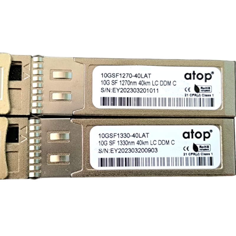
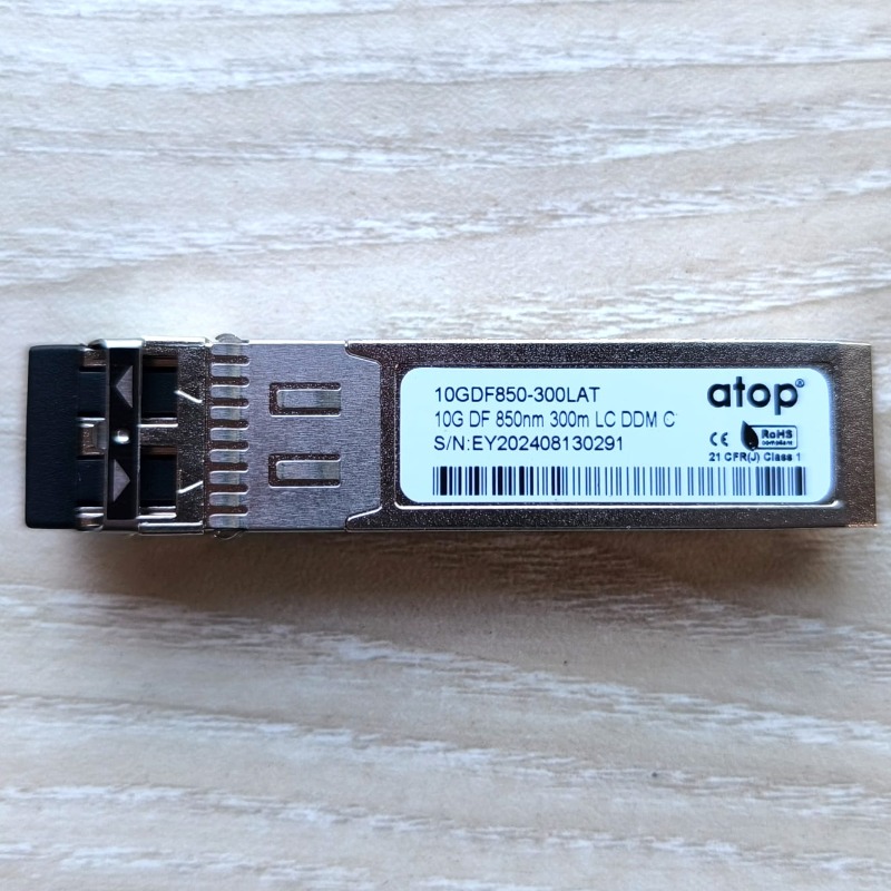
10G SFP+ BIDI Optical Transceiver 40km
Features:
Up to 11.3Gbps Data Links
Up to 40km transmission on SMF Power dissipation<1.0W
1270nm DFB laser and PIN receiver for ESFPB-8823-20DL 1330nm DFB laser and PIN receiver for ESFPB-8832- 40DL 2-wire interface with integrated Digital Diagnostic monitoring EEPROM with Serial ID Functionality
Compliant with SFP+ MSA with LC connector Single + 3.3V Power Supply
Case operating temperature Commercial: 0°C to +70°C Industrial: -40°C to +85°C
Applications:
10GBASE-BX & 10GBASE-LR/LW
10G SONET/SDH, OTU2/2e
Standard:
Compliant with SFF-8472 Compliant to SFF-8431
Compliant to 802.3ae 10GBASE-LR/LW RoHS Compliant.
PRODUCT DESCRIPTION:
ESFPB-88XX-40DL is hot pluggable 3.3V Small-Form-Factor transceiver module. It designed expressly for high-speed communication applications that require rates up to 11.3 Gbps, it designed to be compliant with SFF-8472 and SFP+ MSA. The module data link up to10km in 9/125um single mode fiber.
Absolute Maximum Ratings:
Parameter
Symbol
Min
Typica
Max
Uni
Note
Storage Temperature
Ts
-40
-
85
°C
Relative Humidity
RH
5
-
95
%
Power Supply Voltage
VCC
-0.3
-
4
V
Recommended Operating Conditions:
Parameter
Symbo
Min
Typ.
Max.
Unit
Note
Case Operating Temperature
Tcase
0
-
70
ºC
Commercial
-40
-
85
ºC
Industrial
Power Supply Voltage
VCC
3.14
3.3
3.47
V
Power Supply Current
ICC
-
300
mA
Data Rate
BR
10.312
11.3
Gbps
Transmission Distance
TD
-
40
km
Coupled fiber
Single mode fiber
9/125um SMF
Electrical Characteristics:
Parameter
Symbol
Min.
Type
Max.
Un
Note
Transmitter
Average Launched Power
POut
0
-
5
dB
Average Launched Power (Laser Off)
Poff
-
-
-30
dB
Note (1)
Center Wavelength Range
λC
1260
1270
1280
nm
ESFPB-8823- 40DL
1320
1330
1340
nm
ESFPB-8832- 40DL
Side mode suppression ratio
SMSR
30
-
-
dB
Spectrum Bandwidth(-20dB)
σ
-
-
1
nm
Extinction Ratio
ER
3.5
-
dB
Note (2)
Output Eye Mask
Compliant with IEEE 802.3ae
Note (2)
Receiver
Input Optical Wavelength
λIN
1320
1330
1340
nm
ESFPB-8832- 20DL
1260
1270
1280
nm
ESFPB-8823-20DL
Receiver Sensitivity
Psen
-
-
-15
dB
Note (3)
Input Saturation Power (Overload)
PSAT
0.5
-
-
dB
Note (3)
LOS Assert
LOSA
-30
-
-
dB
LOS De-assert
LOSD
-
-
-17
dB
LOS -Hysteresis
PHys
0.5
-
5
dB
Note:
The optical power is launched into SMF
Measured with RPBS 2^31-1 test pattern @10.3125Gbs
Measured with RPBS 2^31-1 test pattern @10.3125Gbs BER=<10^-12
Electrical Interface Characteristics:
Parameter
Symbol
Min.
Type
Max.
Unit
Note
Total power supply current
Icc
-
300
mA
Transmitter
Differential Data Input Voltage
VDT
180
-
700
mVp-p
Differential line input Impedance
RIN
85
100
115
Ohm
Transmitter Fault Output-High
VFaultH
2.4
-
Vcc
V
Transmitter Fault Output-Low
VFaultL
-0.3
-
0.8
V
Transmitter Disable Voltage- High
VDisH
2
-
Vcc+0.3
V
Transmitter Disable Voltage- low
VDisL
-0.3
-
0.8
V
Receiver
Differential Data Output Voltage
VDR
300
-
850
mVp-p
Differential line Output Impedance
ROUT
80
100
120
Ohm
Receiver LOS Pull up Resistor
RLOS
4.7
-
10
KOhm
Data Output Rise/Fall time
tr/tf
-
38
ps
LOS Fault
VLOS fa
Vcc–
VccHOST
V
LOS Normal
VLOS no
Vee
Vee+0.8
V
Pin Description:
Pin
Symbol
Name/Description
NOT
1
VEET
Transmitter Ground(Common with Receiver Ground)
1
2
TFAULT
Transmitter Fault.
2
3
TDIS
Transmitter Disable. Laser output disabled on high or open.
3
4
SDA
2-wire Serial Interface Data Line
4
5
SCL
2-wire Serial Interface Clock Line
4
6
MOD_A B
Module Absent. Grounded within the module
4
7
RS0
Rate Select 0
5
8
LOS
Loss of Signal indication.Logic 0 indicates normaloperation.
6
9
RS1
No connection required
1
10
VEER
Receiver Ground (Common with Transmitter Ground)
1
11
VEER
Receiver Ground (Common with Transmitter Ground)
1
12
RD-
Receiver InvertedDATAout. AC Coupled
13
RD+
Receiver Non-invertedDATAout. AC Coupled
14
VEER
Receiver Ground (Common with Transmitter Ground)
1
15
VCCR
Receiver Power Supply
16
VCCT
Transmitter Power Supply
17
VEET
Transmitter Ground(Common with Receiver Ground)
1
18
TD+
Transmitter Non-Inverted DATA in. AC Coupled.
19
TD-
Transmitter InvertedDATA in. AC Coupled.
20
VEET
Transmitter Ground(Common with Receiver Ground)
1
Notes:
Circuit ground is internally isolated from chassis ground.
T FAULT is an open collector/drain output, which should be pulled up with a 4.7k – 10k Ohm’s resistor on the host board if intended for use. Pull up voltage should be betwee 2.0V to Vcc + 0.3V.A high output indicates a transmitter fault caused by either the TX bias current or the TX output power exceeding the preset alarm thresholds. A low output indicates normal operation. In the low state, the output is pulled to <0.8V.
Laser output disabled on T DIS >2.0V or open, enabled on TDIS <0.8V.
Should be pulled up with 4.7kΩ- 10kΩ host board to a voltage between 2.0V and 3.6V. MOD_ABS pulls line low to indicate module is plugged in.Internally pulled down per SFF-8431 Rev 4.1.
5.6.LOS is open collector output. It should be pulled up with 4.7kΩ – 10kΩ on host board to a voltage between 2.0V
and 3.6V. Logic 0 indicates normal operation; logic 1 indicates loss of signal.
Digital Diagnostic Functions:
ESFPB88XX-40DL transceivers support the 2-wire serial communication protocol as defined in the SFP+MSA. The standard SFP serial ID provides access to identification information that describes the transceiver’s capabilities, standard interfaces, manufacturer, and other information.
Additionally, SFP+ transceivers provide a unique enhanced digital diagnostic monitoring interface, which allows real-time access to device operating parameters such as transceiver temperature, laser bias current, transmitted optical power, received optical power and transceiver supply voltage. It also defines a sophisticated system of alarm and warning flags, which alerts end-users when particular operating parameters are outside of a factory set normal range.
The SFP MSA defines a 256-byte memory map in EEPROM that is accessible over a 2-wire serial interface at the 8 bit address 1010000X (A0h). The digital diagnostic monitoring interface makes use of the 8-bit address 1010001X (A2h), so the originally defined serial ID memory map remains unchanged.
The operating and diagnostics information is monitored and reported by a Digital Diagnostics Transceiver Controller (DDTC) inside the transceiver, which is accessed through a 2-wire serial interface. When the serial protocol is activated, the serial clock signal (SCL, Mod Def 1) is generated by the host. The positive edge clocks data into the SFP transceiver into those segments of the E2PROM that are not write- protected. The negative edge clocks data from the SFP transceiver. The serial data signal (SDA, Mod Def 2) is bi-directional for serial data transfer. The host uses SDA in conjunction with SCL to mark the start and end of serial protocol activation. The memories are organized as a series of 8-bit data words that can be addressed individually or sequentially.
Recommended Interface Circuit:
Outline Dimensions:
Order Information:
Part Number
Product Description
10GSF1270-40LAT
BIDI SFP+ Tx1270nm/Rx1330nm 40km LC DDM
10GSF1330-40LAT
BIDI SFP+ Tx1330nm/Rx1270nm 40km LC DDM
No Review Found.
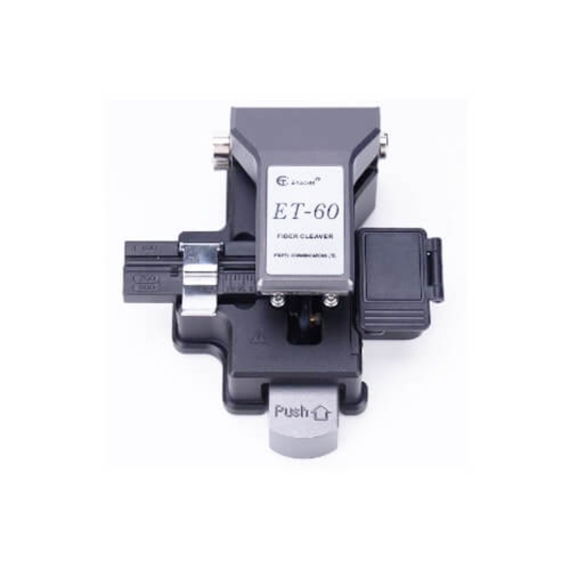
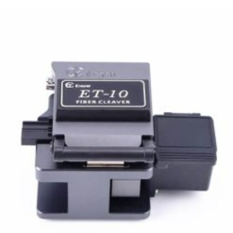
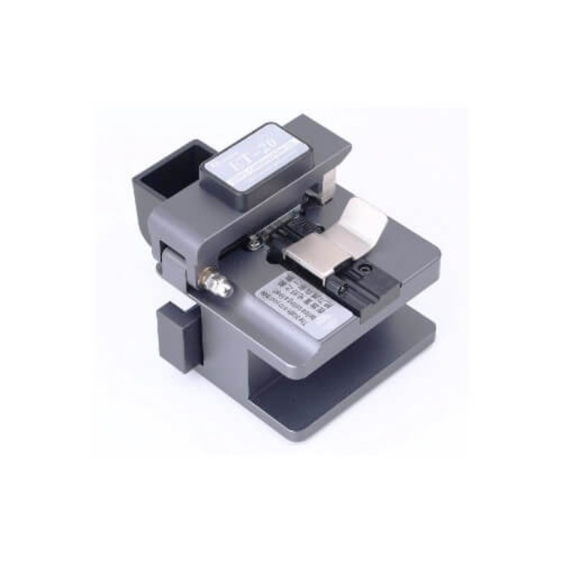
Related Products
-0%

-0%
-0%

-0%
-4%
-0%
-0%
-0%
-0%
-3%
-0%
-2%
Sign up to newslatter
No Excuse Make Effort
Login To Comment